-
BEFORE YOU START
-
PLATFORM SERIES DESK - PARTS LIST
-
TOOLS AND HARDWARE BAGS
-
ASSEMBLING THE PLATFORM SERIES DESK
-
MONITOR ARM(S) - PARTS LIST
-
MONITOR ARM(S) - ASSEMBLING
-
ADDITIONAL FEATURES
-
DESK EXTENSIONS AND SIDE PEGBOARDS KIT - PARTS LIST
-
ASSEMBLING THE EXTENSIONS AND PEGBOARDS KIT
-
POWER RATING
-
WARRANTY
-
LEGAL
- RELATED CONTENT
MANUAL | QUICK START GUIDE
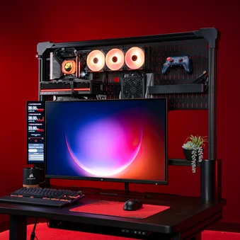
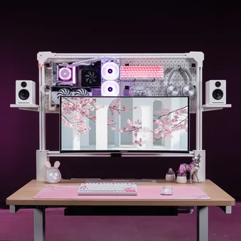
PLATFORM SERIES
MODULAR COMPUTER DESKS

BEFORE YOU START
Congratulations on purchasing your new CORSAIR Platform Series Desk.
Please take a moment to carefully read this guide prior to assembling.
PLATFORM SERIES DESK - PARTS LIST
LARGE ITEMS LIST
* Not available with Platform:4
** Sold separately on some models

Desk Surface (1x)

T-Channel Rail (1x)

Feet (2x)

Right and Left Legs (1x each)

D-Brackets (2x)

Wire Management Tray (1x)

Crossbeam Support Bar (1x)

Right and Left Corner Supports (1x each)

3-Port Power Strip (1x)

Cubby Module (1x)
(Preinstalled with Platform:6)

SMALL ITEMS LIST
* Not available with Platform:4
** Sold separately on some models
*** Elevate models only

M4 15mm Bolts (2x)

M6 10mm Bolts (8x)

M6 15mm Bolts (10x)

M8 15mm Bolts (16x)

M6 Black T-Nuts (10x)

1/4" 20 Silver T-Nuts (6x)

Wing Nut Screws (2x)
Ratcheting Bolts (2x)

Power Strip Rail Mount (1x)

Power Strip Desk Mount (1x)

Controller (1x)

Straight Cable Channels (2x)

Curved Cable Channels (2x)

Power Supply (1x)

Small Wire Management Trays (2x)
(1x with Platform:4)

Elgato Flex Arm Adapter (1x)
Elgato Multi Mount Adapter (2x)

Support Bar Covers (2x)

Wood Dowels (4x)

Power Cable (1x)

Buckle Velcro Ties (10x)
Velcro Ties (10x)

Ratcheting Wrench and 5mm Hex Bit (1x)

3mm Hex Tool (1x)

5mm Hex Tool (1x)

Hex / Phillips Combo Tool (1x)

Cable Clips (6x)
(5x with Platform:4)
TOOLS AND HARDWARE BAGS

STEP 1 HARDWARE
M8 15mm Bolts (16x)

STEP 2 HARDWARE
M6 10mm Bolts (2x)
M6 15mm (4x)
Wing Nut Screws (2x)

STEP 3 HARDWARE
M4 15mm Bolts (2x)
M6 15mm Bolts (2x)
STEP 5 HARDWARE
Ratcheting Bolts (2x)
Wooden Dowels (4x)

STEP 6 HARDWARE
M6 10mm Bolts (6x)

BLACK T-NUTS
M6 Black T-Nuts (10x)

SILVER T-NUTS
1/4" 20 Silver T-Nuts (6x)

TIES
Buckle Velcro Ties (10x)
Velcro Ties (10x)

SPARE PARTS (EXTRAS)
T-Nut Set Screws (3x)
M6 10mm Bolts (4x)
M6 15mm Bolts (4x)
M8 15mm Bolts (2x)
Wooden Dowels (2x)
ASSEMBLING THE PLATFORM SERIES DESK
Lay the desk surface down on a piece of cardboard, a blanket, or a rug.

1: ATTACHING THE LEGS AND THE FEET
To complete the step, the following hardware and tools will be used:

Feet (2x)

Right and Left Leg (1x each)

M8 15mm Bolt (16x)

Ratcheting Wrench and 5mm Hex Bit (1x)

5mm Hex Tool (1x)
- Note the L and R marks on each of the legs.
- Install the Right and Left Legs (4) and secure each with four M8 15mm Bolts (D).

- Place the Feet (3) onto the Right and Left Legs (4) and secure each with four M8 15mm Bolts (D).

2: INSTALLING THE WIRE MANAGEMENT TRAY
To complete the step, the following hardware and tools will be used:

D-Brackets (2x)

Wire Management Tray (1x)

M6 10mm Bolts (2x)

M6 15mm Bolts (4x)

Wing Nut Screws (2x)
Ratcheting Wrench and 5mm Hex Bit (1x)
5mm Hex Tool (1x)
- Attach the two D-Brackets (5). Pay attention to the correct orientation as illustrated below.
- Secure each with two M6 15mm Bolts (C).
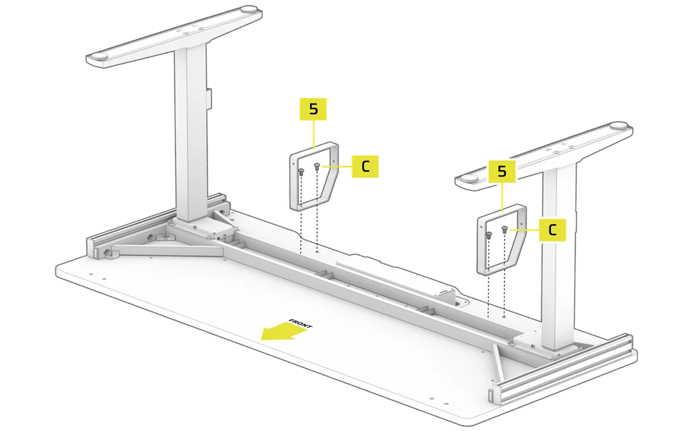
- Place the Wire Management Tray (6) over the D-Brackets (5).
- Secure the front of the Wire Management Tray (6) with two Wing Nut Screws (F).

- Secure the rear of the Wire Management Tray (6) with two M6 10mm Bolts (B).

3: INSTALLING THE CONTROLLER AND THE POWER SUPPLY
To complete the step, the following hardware and tools will be used:

M4 15mm Bolts (2x)

M6 15mm Bolts (2x)

Controller (1x)

Power Supply (1x)

Power Cable (1x)
Ratcheting Wrench and 5mm Hex Bit (1x)
5mm Hex Tool (1x)

Hex / Phillips Combo Tool (1x)

Cable Clips (6x)
(4x with Platform:4)
- Place the Controller (K) over the pre-drilled holes in the desk as shown on the image, and secure it with two M6 15mm Bolts (C).

- Install the Cable Clips (Z) by pushing them firmly into the holes located on the bottom side of the desk.

- Place the Power Supply (M) between the rails with the HS port facing the previously installed Controller (K) and secure it using two M4 15mm Bolts (A).

- Wire the two motors (Ω) to the M1 and M2 ports on the Power Supply (M).
- Wire the Controller (K) to the HS port on the Power Supply (M).
- Plug the Power Cable (S) to the AC port on the Power Supply (M).
- Route the cables through the Cable Clips to keep them secure.

4: INSTALLING THE CUBBY MODULE AND THE CROSSBEAM SUPPORT BAR
To complete the step, the following hardware and tools will be used:

Crossbeam Support Bar (1x)

Cubby Module (1x)

Support Bar Covers (2x)
Ratcheting Wrench and 5mm Hex Bit (1x)
5mm Hex Tool (1x)
- Flip the desk onto its feet.

- Slide the Cubby Module (11) assembly into the empty slot on the tabletop. The module will click once it is fully seated.

- Attach the Crossbeam Support Bar (7) by aligning its large holes over the half-threaded bolts on the rear of the legs.
- Push the Crossbeam Support Bar (7) down until it is even on both sides.
- Once secure, tighten the bolts fully.

- Carefully but firmly snap the Support Bar Covers (Q) over the ends of the Crossbeam Support Bar (7).

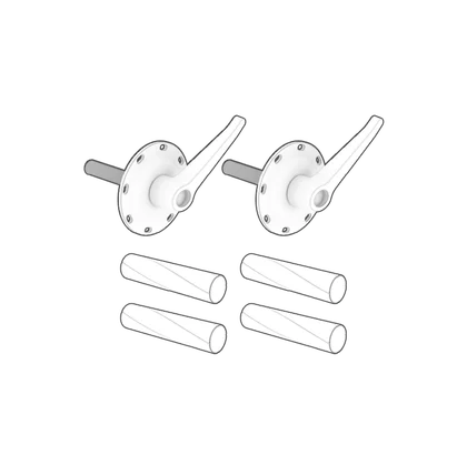
5: T-CHANNEL RAIL ASSEMBLY
To complete the step, the following hardware and tools will be used:

T-Channel Rail (1x)

Right and Left Corner Supports (1x each)
M6 15mm Bolts (2x)

Ratcheting Bolts (2x)

Wood Dowels (4x)
Ratcheting Wrench and 5mm Hex Bit (1x)

3mm Hex Tool (1x)
5mm Hex Tool (1x)
- Insert two Wood Dowels (R) into the alignment holes on both the left and right ends of the desk.
- Lower the Left Corner Support (8) onto the Wood Dowels (R).
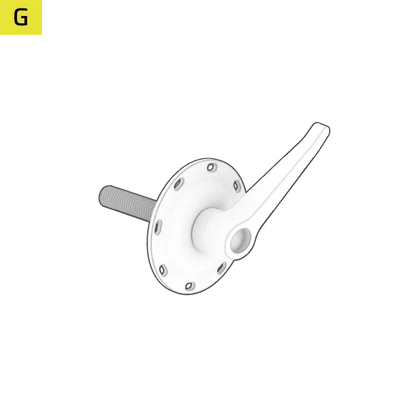
- Align the Left Corner Support (8) and secure it fully to the desk using the Ratcheting Bolt (G).

- Tighten the Ratchet Bolt (G) by rotating the lever clockwise.
- Pull the Ratchet Bolt (G) lever downwards and rotate it counterclockwise.

- Repeat until secure.
- Alternatively, pull and hold the Ratchet Bolt (G) lever down and tighten it using the 5mm Hex Tool (X).

- Slide the T-Channel Rail (2) over the horizontal T-Nuts on the Left Corner Support (8) but do not tighten the set screws inside the T-Nuts yet.

- Slide the T-Channel Rail (2) over the horizontal T-Nuts on the Right Corner Support (8) but do not tighten the set screws inside the T-Nuts yet.
- Lower the Right Corner Support (8) with the attached T-Channel Rail (2) onto the Wood Dowels (R) and secure it fully to the desk using the Ratcheting Bolt (G).

- Using a 3mm Hex Tool (W), tighten the four set screws inside the T-Nuts until the T-Channel Rail (2) is rigid and sturdy.

6: T-NUTS, POWER STRIPS AND WIRE MANAGEMENT INSTALLATION (OPTIONAL)
To complete the step, the following hardware will be used:
** Sold separately on some models

3-Port Power Strip (1x)

M6 10mm Bolts (10x)

M6 Black T-Nuts (10x)

Power Strip Rail Mount (1x)

Power Strip Desk Mount (1x)

Straight Cable Channels (2x)

Curved Cable Channels (2x)

Small Wire Management Trays (2x)
(1x with Platform:4)

Buckle Velcro Ties (10x)

Velcro Ties (10x)
3mm Hex Tool (1x)
5mm Hex tool (1x)
Hex / Phillips Combo Tool (1x)
T-NUTS INTALLATION
T-Nuts allow you to add accessories and extensions to the Platform's T-Channel Rail system. The black T-Nuts are M6 threaded and used for assembly of extensions and accessories. The silver T-Nuts are quarter-inch threaded and are compatible with Elgato mount products.
To add and secure a T-Nut to a T-Channel Rail, follow the next steps:


1. Rotate the T-Nut horizontally.
2. Slide the T-Nut into the T-Channel Rail sideways.


3. Once the T-Nut is in the slot, rotate it back to its correct orientation.
4. Using a 3mm Hex Tool, tighten the set screw inside the T-Nut to secure it in place.
POWER STRIP AND WIRE MANAGEMENT INSTALLATION
The 3-Port Power Strip can be clamped to the desk or attached to the T-Channel Rail system.

CLAMPING THE 3-PORT POWER STRIP TO THE DESK (OPTIONAL)
- Find a suitable position on the desk and secure the Power Strip Desk Mount (I) with the mounted 3-Port Power Strip (9) by tightening the hand knob screw clockwise.
- Plug the power cord into an electrical outlet.

ATTACHING THE 3-PORT POWER STRIP TO THE RAIL SYSTEM (OPTIONAL)
- Using the Hex / Phillips Combo Tool (Y), loosen and remove the Phillips center screw of the Power Strip Desk Mount (I) and slide the 3-Port Power Strip (9) out of the mount plate.
- Insert two M6 Black T-Nuts (E1) into the back of the T-Channel Rail (2). Do not tighten the set screws yet.

- Align the mounting bracket holes of the Power Strip Rail Mount (H) with the holes in the M6 Black T-Nuts (E1).
- Loosely secure the Power Strip Rail Mount (H) to the M6 Black T-Nuts (E1) by screwing in two M6 10mm Bolts (B) and slide the Power Strip Rail Mount (H) to the desired position.
- Slide the 3-Port Power Strip (9) onto the mounting bracket of the Power Strip Rail Mount (H) from the open side and secure it with the previously removed Phillips center screw.
- Tighten all the bolts.

INSTALLING THE SMALL WIRE MANAGEMENT TRAYS (OPTIONAL)
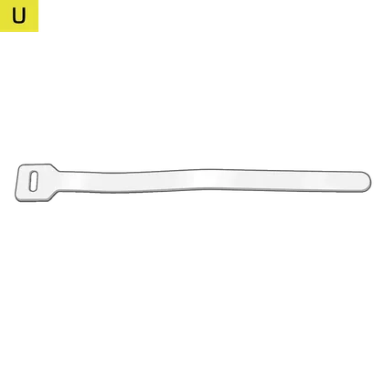
You can use the included Small Wire Management Tray (N) to clean up your workspace by tying down the cables with the included Velcro Ties (T and U).
- Insert two M6 Black T-Nuts (E1) into the back of the T-Channel Rail (2). Do not tighten the set screws yet.
- Align the mounting holes of the Small Wire Management Tray (N) with the holes in the M6 Black T-Nuts (E1).
- Loosely secure the Small Wire Management Tray (N) to the M6 Black T-Nuts (E1) by screwing in two M6 10mm Bolts (B).
- Slide the Small Wire Management Tray (N) to the desired position.
- Secure the Small Wire Management Trays (N) to the M6 Black T-Nuts (E1) by tightening the two M6 10mm Bolts (B).
- Install the second Small Wire Management Tray (N) by following the same process.

ATTACHING THE CABLE CHANNELS (OPTIONAL)
You can use the included Cable Channels (L1 and L2) to clean up your workspace by tying down the cables with the included Velcro Ties (T and U). Straight (L1) and Curved Cable Channels (L2) can snap together to help you route and conceal cables down the corner supports.

- Insert two M6 Black T-Nuts (E1) into the back of the T-Channel Rail (2). Do not tighten the set screws yet.
- Align the mounting holes of the Straight Cable Channel (L1) with the holes in the M6 Black T-Nuts (E1).
- Loosely secure the Straight Cable Channel (L1) to the M6 Black T-Nuts (E1) by screwing in two M6 10mm Bolts (B).
- Slide the Cable Channels (L1 and L2) to the desired position.
- Secure the Straight Cable Channel (L1) to the M6 Black T-Nuts (E1) by screwing in two M6 10mm Bolts (B).
- Mount the second Cable Channel by following the same process.

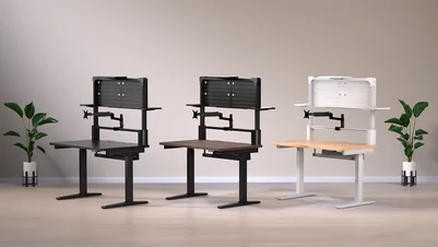
7: ADJUSTING THE DESK HEIGHT
- Press and hold the Raise button (a) to raise the desk.
- Press and hold the Lower button (b) to lower the desk.

- Press and hold either the Preset 1 or Preset 2 buttons (e or f) for five seconds to save the current height as a preset to that button.

- Press either Preset button (e or f) to adjust the desk to the preset height.

By default, the LCD display (c) shows the current height of the desk in centimeters. You can change the controller to display the height in inches by doing the following:
- Press and hold the S button (d) for five seconds until the LCD display (c) starts blinking "UN".

- Once the LCD display (c) is blinking "UN", press either the Raise or Lower Button (a or b) to change the units from centimeters ("SI" shown on the display) to inches ("IN" shown on the display), or vice versa.

- Press the S button (d) to lock the chosen selection.

TROUBLESHOOTING AND ERROR CODES EXPLANATION
| E02 | Vibration, interference or tilt sensed during operation. |
| Stop the adjustment immediately and allow the desk to reverse or stop moving. Confirm that no obstruction is in place before continuing. If the error message does not disappear on its own, press and hold the Lower button (b) for three to five seconds to reset. |
| HOT | Overheating protection triggered. |
| Stop the adjustment immediately. Wait for 18 minutes and the error message should disappear. If the error message does not disappear on its own, press and hold the Lower button (b) for three to five seconds to reset. |
| E20 | Desk overload protection triggered. |
| Remove weight or heavy objects from the desk before continuing. If this error appears while lowering the desk and does not disappear on its own, press and hold the Lower button (b) for three to five seconds to reset. |
| E10 | Motor malfunction protection. |
| Disconnect power. Ensure the motor connection to the controller is secure. Reconnect power. If the error message does not disappear on its own, press and hold the Lower button (b) for three to five seconds to reset. |
| E60 | Out of sync protection. |
| Disconnect the power to reset. Ensure the connections between both motors and the power supply, as well as the connection between the power supply and the controller are secure. Reconnect power. If the error message does not disappear on its own, press and hold the Lower button (b) for three to five seconds to reset. |
| RES | Sudden power loss detected. |
| Press and hold the Lower button (b) for three to five seconds to reset. |
MONITOR ARM(S) - PARTS LIST
* Not available with Platform:4
M4 25mm Bolts (8x)
(4x with Platform:4)

Gas Spring Arms (2x)
(1x with Platform:4)

Extension Arms (2x)
(1x with Platform:4)

Connector (1x)

Mounting Bracket (1x)

Inclined Covers (2x)
(1x with Platform:4)

Flat Covers (2x)

Strip Covers (4x)
(2x with Platform:4)

VESA Mount (2x)
(1x with Platform:4)

Plastic Spacers (8x)
(4x with Platform:4)

Zip Ties (10x)

3mm Hex Tool (1x)

4mm Hex Tool (1x)

5mm Hex Tool (1x)

6mm Hex Tool (1x)
MONITOR ARM(S) - ASSEMBLING
1: INSTALLING THE MOUNTING BRACKET AND THE CONNECTOR
To complete the step, the following hardware and tools will be used:

Connector (1x)
(Platform:6 only)

Mounting Bracket (1x)

4mm Hex Tool (1x)

6mm Hex Tool (1x)
- Swing the bottom part of the Mounting Bracket (E) open by loosening the hand knob screw and rotating it 180°.
- Place the Mounting Bracket (E) over the T-Channel Rail (2) with the post in the rear and slide the assembly to the desired location.
- Rotate the bottom part of the Mounting Bracket (E) back to closed position and tighten the hand knob screw and the locking screw.

- Loosen the Mounting Bracket (E) locking ring by holding its top part with one hand and unscrewing the bottom notched part with the other hand. Remove the ring by sliding it off the post.
- Using a 6mm Hex Tool (O), loosen the collar bolt of the Connector (D), allowing it to open a bit.

- Slide the Connector (D) over the post of the Mounting Bracket (E), adjust it to the desired height and retighten the collar bolt.
- Slide the Mounting Bracket (E) locking ring over the Connector (D) and secure it.

2: ASSEMBLING AND ATTACHING THE ARM(S)
To complete the step, the following hardware and tools will be used:

Gas Spring Arms (2x)
(1x with Platform:4)

Extension Arms (2x)
(1x with Platform:4)

Inclined Covers (2x)
(1x with Platform:4)

Flat Covers (2x)
(Platform:6 only)

5mm Hex Tool (1x)
- Using a 5mm Hex Tool (N), remove the bolt and washers of the Inclined Cover (F). Be careful not to lose the washers.
- Place the Gas Spring Arm (B) over the socket of the Extension Arm (C) like shown on the image.
- Secure the assembly with the previously removed bolt and washers and tighten.
- Following the same procedure, assemble the second arm (Platform:6 only).

If you are assembling a dual monitor arm ...
- Using a 5mm Hex Tool (N), remove the bolt and washers of the Flat Cover (G). Be careful not to lose the washers.
- Slide the assembled arm over the post of the Connector (D).
- Insert the Flat Cover (G) and secure it with the previously removed bolt and washers. Make sure the Flat Cover (G) sits flush in the opening.
- Tighten the Flat Cover (G) bolt.
- Following the same procedure, attach the second arm.

If you are assembling a single monitor arm ...
- Loosen the Mounting Bracket (E) locking ring and adjust it to the desired height position.
- Tighten the Mounting Bracket (E) locking ring to secure it.
- Slide the assembled arm over the post of the Mounting Bracket (E).

3: ATTACHING THE MONITOR
To complete the step, the following hardware will be used:

M4 25mm Bolts (8x)
(4x with Platform:4)

VESA Mounts (2x)
(1x with Platform:4)

Plastic Spacers (8x)
(4x with Platform:4)
- Remove the monitor stand from your VESA-compatible monitor.
- Screw the VESA Mount (I) onto the back of your monitor, ensuring the flatter side of the plate is oriented towards the top of your monitor.

- Slide the monitor into the opening on the head of the Gas Spring Arm (B) while pulling the pin to fully secure and lock the monitor into place.

4: SPRING TENSION ADJUSTMENT AND CABLE MANAGEMENT
To complete the step, the following hardware and tool will be used:

Strip Covers (4x)
(2x with Platform:4)
4mm Hex Tool (1x)
- To adjust the tension of the Gas Spring Arm (B), tilt the arm downwards to expose the adjustment bolt.
- Increase the spring tension by turning the screw counterclockwise. Reduce the spring tension by turning the screw clockwise.

- Tuck away the cable from your monitor into the rubber push-fit channel on the Extension Arm (C).
- On the Gas Spring Arm (B), hide the monitor cable into the metal channel and cover it by snapping in a Strip Cover (H).

ADDITIONAL FEATURES
Platform Series desks include useful additional features enabled by two optional accessories. To browse compatible products (sold separately), please visit www.elgato.com.
To mount Elgato accessories, use the following hardware:

1/4" 20 Silver T-Nuts (6x)

Elgato Flex Arm Adapter (1x)
Elgato Multi Mount Adapter (2x)
ELGATO FLEX ARM ADAPTER
- Mount the Elgato Flex Arm Adapter (O) to the T-Channel Rail (2), using the silver 1/4" 20 Silver T-Nuts (E2), to the pre-threaded holes on the top of the Corner Supports (8) or to the pre-threaded hole on the top of the monitor arm Mount Bracket (E)

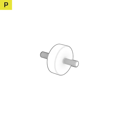
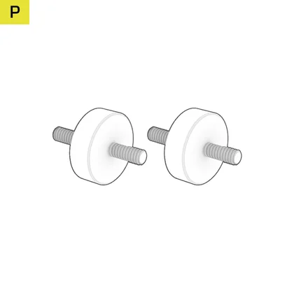
ELGATO MULTI MOUNT ADAPTER
- First remove the three screws from the bottom of your Elgato Multi Mount product.
- Mount the Elgato Multi Mount Adapter (P) to the T-Channel Rail (2), using the silver 1/4" 20 Silver T-Nuts (E2) or to the pre-threaded holes on the top of the Corner Supports (8).

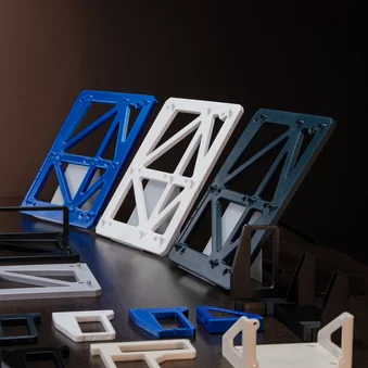
DESK EXTENSIONS AND SIDE PEGBOARDS KIT - PARTS LIST
To add more surface area to your Platform desk, you can add extensions or pegboards on one or both sides (sold separately).

LARGE ITEMS LIST

Desk Extensions (2x)

T-Support (2x)

Side Pegboard (2x)
SMALL ITEMS LIST
M6 10mm Bolts (12x)

Pegboard Push Button Mounts (3x)
M6 Black T-Nuts (12x)

Short Pegboard Hooks (3x)

Long Pegboard Hooks (3x)

L-Shaped Pegboard Hooks (4x)

Wide Pegboard Hooks (2x)

Pegboard Multi-hook (1x)
Straight Cable Channel (1x)
Curved Cable Channel (1x)
Buckle Velcro Ties (5x)

Zip Ties (10x)
3mm Hex Tool (1x)
5mm Hex Tool (1x)
ASSEMBLING THE EXTENSIONS AND PEGBOARDS KIT
1: INSTALLING THE DESK EXTENSIONS
To complete the step, the following hardware and tool will be used:

Desk Extensions (2x)

M6 10mm Bolts (6x)

M6 Black T-Nuts (6x)
5mm Hex Tool (1x)
- Insert three M6 Black T-Nuts (E1) into the side rails under the desk, marked in the locations indicated by the thicker vertical lines, as shown on the image below.
- Insert two M6 10mm Bolts (B) into the top two Black M6 T-Nuts (E1) only and screw them approximately halfway in.

- Place the Desk Extension (12) over the half-screwed M6 10mm Bolts (B).
- Push the Desk Extension (12) so that the M6 10mm Bolts (B) wedge into the narrower grooves of the mounting holes.

- Insert an M6 10mm Bolt (B) into the bottom mounting hole of the Desk Extension (12).
- Secure the Desk Extension (12) by tightening all three M6 10mm Bolts (B).

- Repeat the process if you wish to mount an additional Desk Extension on the opposite side of the desk.
2: INSTALLING THE SIDE PEGBOARDS
To complete the step, the following hardware and tool will be used:

T-Supports (2x)

Side Pegboards (2x)

M6 10mm Bolts (12x)
M6 Black T-Nuts (6x)

Short Pegboard Hooks (3x)

Long Pegboard Hooks (3x)

L-Shaped Pegboard Hooks (4x)
Wide Pegboard Hooks (2x)

Pegboard Multi-hook (1x)
3mm Hex Tool (1x)
- Insert three M6 Black T-Nuts (E1) into the side rails under the desk, marked in the locations indicated by the thicker vertical lines, as shown on the image below.

- Secure the T-Support (13) to the M6 Black T-Nuts (E1) using three M6 10mm Bolts (B).
- Align the Pegboard (14) to the T-Support and secure it using three M6 10mm Bolts (B), as shown on the image below.

- Repeat the process if you wish to mount an additional Side Pegboard (14) on the opposite side of the desk.
- Mount the hooks onto the Side Pegboard (14) by inserting them through the holes. You can use any position on the Pegboard.
POWER RATING
Input voltage: AC100-240V
Frequency: 50-60Hz/4A (max)
WARRANTY

Platform Series desks have a 5-year warranty.
LEGAL
©2023-2025 CORSAIR MEMORY, Inc. Trademarks belong to their respective owners. All rights reserved.
RELATED CONTENT