MANUAL | QUICK START GUIDE
CORSAIR 5000T & 5000T LX RGB

CASE SPECIFICATIONS
|
Dimensions |
530 x 560 x 251mm |
|
PCI Slot Configuration |
7 Horizontal / 3 Vertical |
|
Motherboard Compatibility |
Mini-ITX, Micro-ATX, ATX, E-ATX (305mm x 277mm) |
|
HDDs |
3x |
|
SSDs |
7x |
|
Fan Support |
Front: 3x 120mm, 2x 140mm |
|
Top: 3x 120mm, 2x 140mm |
|
|
Side: 3x 120mm |
|
|
PSU Shroud: None |
|
|
Rear: 1x 120mm |
|
|
Radiator Compatibility |
Front: 360mm, 280mm, 240mm |
|
Top: 360mm, 280mm, 240mm |
|
|
Side: 360mm, 240mm |
|
|
PSU Shroud: None |
|
|
Rear: 120mm |
|
|
Included Fans |
5000T: None 5000T LX RGB: 3x iCUE LINK LX120 RGB Fans Pre-Installed |
|
Included Controllers |
5000T: None 5000T LX RGB: iCUE LINK System Hub + iCUE LINK RGB Adapter |
|
Colors Available |
White; Black |
|
Left Side Panel Material |
Tempered Glass |
|
Front Panel Material |
Airflow-Optimized Y-Mesh |
|
Max GPU Length |
450mm |
|
Max CPU Cooler Height |
170mm |
|
Max PSU Length |
250mm |
|
Rear Cable Space |
46mm |
|
Dust Filters |
Front, Top, Side, PSU |
|
Front I/O |
4x USB 3.2 Gen 1 Type A, 1x USB 3.2 Gen 2 Type C, 1x PWR, 1x Combo Mic/Headphone, 1x Reset Button |

ACCESSORY KIT CONTENTS

Fan Washers
QuikTurn™ Fan Screws

SSD Screws (M3 x 0.5; 5mm)

Motherboard/HDD Screws
(6-32; 6mm)

Spare Motherboard Standoff

Zip Ties

Vertical Mount Standoffs

Front I/O Adapter

CASE EXPLODED VIEW

- Tempered Glass Side Panel
- Mesh Front Panel
- Steel Side Panel
- Front Panel
- Front Fan Filter
- Top Panel
- Top Fan Filter
- PSU Shroud Cover
- PSU Fan Filter
- PCI Plate
- Drive/Controller Plate
- SSD Tray
- iCUE LINK System Hub (LX RGB Only; *Not pictured)
- iCUE LINK System Hub Power Cable (LX RGB Only; *Not pictured)
- iCUE LINK System Hub USB Cable (LX RGB Only; *Not pictured)
- iCUE LINK Cable (LX RGB Only; *Not pictured)
- GPU Anti-Sag Arm and Mount
- Side Fan/Radiator Mount
- HDD Tray
- HDD Cage
PANEL INSTALLATION/REMOVAL
|
WARNING: This product is made with Tempered Glass. Avoid storage on or contact with hard surfaces like ceramic/porcelain tile, stone, masonry, or concrete. CORSAIR recommends removing all tempered glass side panels before placing the case or building on a hard surface. If necessary to place your finished build on a hard surface, it is recommended to elevate or isolate your case from the surface to avoid accidantal contact, potential damage, or injury. Handle glass with care. Replacement panels are available at corsair.com. Contact help.corsair.com for any assistance. |

Side Panels
- The 5000T has two hinged doors that are secured with snaps and optional screws.
- To open the tempered glass panel, pull the panel from the front edge of the case towards the back and hinge the panel open.
- To remove the panel from the case, ensure there is no locking screw on the hinge and lift the panel off of the two hinge mounts.

- To open the steel panel, pull the panel from the front edge of the case towards the back and hinge the panel open.

Front Panel
- Remove the mesh front panel, pull the panel outward. It's secured by two magnets at the top and bottom.

Top Panel
- Remove the mesh top panel, grab the top panel at the back of the case and pull it upward and towards the front of the case.
Side Fan Mount
- The fan mount can be removed by unscrewing the 6x screws holding the mount in place.
INSTALLING HARDWARE

Installing a Motherboard
- The 5000T supports mITX, mATX, ATX, and E-ATX motherboards, including ASUS BTF, MSI Project Zero, and Gigabyte Project Stealth with reversed power connections.
- Ensure the I/O plate or shield is installed if required.
- Align the motherboard with the standoffs and secure it with the provided screws.
Tip: If standoffs don’t align, move unused ones to the appropriate slots in the tray.
Installing the Front Panel I/O Cables
- Connect the FPANEL plug directly to your motherboard front panel I/O pins, following the keyed connector.

- For non-standard Intel or AMD motherboards, use the included adapter to connect from the FPANEL plug to the individual pins.

| TIP: If your PC experiences issues or doesn't turn on with the FPANEL plug, consider trying the adapter cable. |

| Radiator Mounting Locations | |
|
Top |
Front: 360mm, 280mm, 240mm |
|
Front |
Top: 360mm, 280mm, 240mm |
|
Side |
Side: 360mm, 240mm |
|
Bottom |
PSU Shroud: None |
|
Rear |
Rear: 120mm |
Installing a Radiator
- 5000T features radiator mounts in the front, top, rear, and sides of the case.
| TIP: For optimal noise, thermal performance, and reliability, ensure the radiator is mounted higher than the pump when using an AIO. |
- For AIO coolers, top mounting provides the optimal balance of performance and compatibility, but other mounts can be utilized based on your build preferences. Consult your coolers product manual for more tips on usage and best practices.

Installing a Graphics Card or Expansion Card
- The 5000T supports both horizontal and vertical GPU installations using the installed PCI bracket.
- After installing the motherboard, remove the PCI cover screws to fit the GPU.

- Slide the card in until the PCIe retention clicks on the motherboard.
- Align screws in the PCIe shield and secure the expansion card into the case.

| TIP: Add the GPU as one of the final steps for easier building. |
Installing a GPU in a Vertical Orientation
- The 5000T supports vertical GPU mounting with the included PCI plate and a PCIe Riser Card (sold separately).
- Start by removing the four screws from the PCI plate at the rear of the case.

- Uninstall the plate and rotate it 90°, with the thumbscrews for the GPU facing the top of the PCI hole.
- Reinstall the four screws removed from the plate prior.

- Install the vertical GPU standoffs included in the accessory box.

- Mount the riser to the standoffs using two of the included 6-32 motherboard screws.

- Mount the GPU into the rear PCI plate, clicking it into the riser card, and secure the card with the thumbscrews.

Installing HDDs, SSDs, or Controllers

For Drives
- The 5000T includes a combo drive/controller plate and several SSD trays, with the combo plate accommodating 1x HDD or 2x SSDs.
- To remove a drive plate, unscrew the single retaining screw and remove the plate.

- Using the included screws found in the accessory box, attach a HDD to the drive plate by inserting the screws through the plate and into the bottom of the drive.
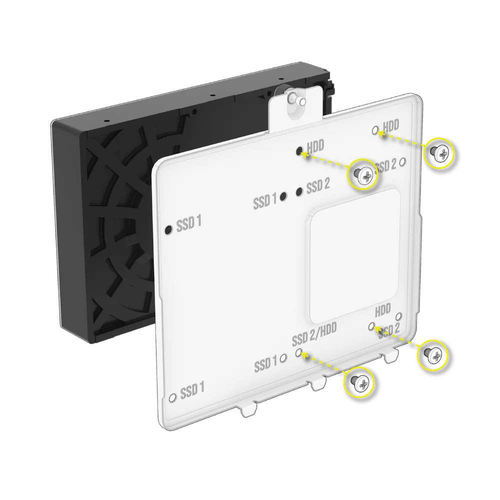
- Using the included screws found in the accessory box, attach a SSD to the drive plate by inserting the screws through the plate and into the bottom of the drive

- The drive plate also doubles as a home for an iCUE LINK System Hub controller if one is in use.

- Three additional SSD mounts sit below the combination drive/controller plate.
- Install SSDs by using the provided screws from the bottom of the drive.

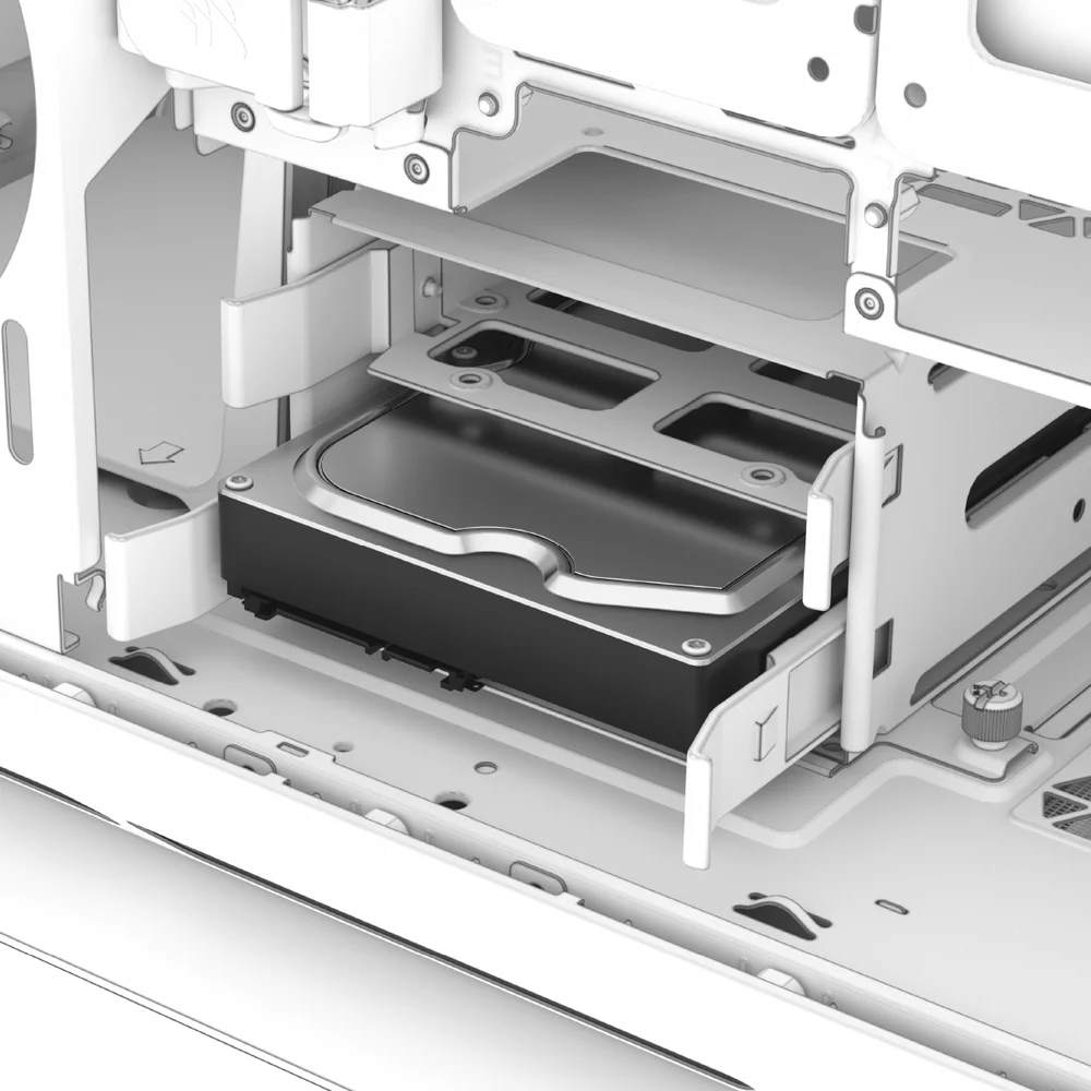
- Additionally, you can add two more HDDs in the HDD cage below the PSU shroud.
| TIP: HDD trays may be repurposed to fit additional 2.5" SSDs. |
| TIP: HDD cage may be removed entirely to make more space if you are not utilizing the cage. |
Installing a Standard Power Supply

- Slide the PSU into the PSU location with the fan facing down.

- Secure the screws to the PSU exhaust area.
Installing a CORSAIR SHIFT Power Supply
- The 5000T is fully compatible with all SHIFT power supplies and installs identically to a standard ATX PSU.

Installing Fans

| Fan Mounting Locations | |
|
Top |
3x 120mm, 2x 140mm |
|
Front |
3x 120mm, 2x 140mm |
|
Side |
3x 120mm |
|
Bottom |
None |
|
Rear |
1x 120mm |
- The 5000T can mount up to 10x 120mm or 4x 140mm on the top, side, and rear of the case.
- To install fans in the front, side, or top, align your fans to the fan mounting slots, and screw an included QuikTurn fan screw into the fan frame.

MAINTENANCE
Cleaning Your Case Filters
- The 5000T features four removable dust filters. A power supply filter on the bottom, a magnetic filter on the top and side, as well as a plastic/nylon filter on the front.
- To remove the filter from the front panel, remove the front panel and unscrew the 4x screws holding the filter to the front panel assembly. You may also clean or dust the filter without fully disassembling for more convenience.

- The PSU filter pulls straight back from the PSU.

- The top and side filter are magnetic and can be reached by removing the top or side panels that cover them.


Tip: Filters can be cleaned with pressurized air or water. If you rinse your filter, ensure filters are fully dry before reinstalling.
Frequently Asked Questions
- Does the polarity matter with the I/O panel’s power and reset header?
No, only the LED headers. - Who should I contact if I received my case damaged or one of the fans is no longer working?
Please go to support.corsair.com and request an RMA so that we can replace the damaged part(s).
WIRING YOUR iCUE LINK CONTROLLER FOR DIGITAL RGB CONTROL
Connecting the Included Controller to PC
Connect the iCUE LINK System Hub to USB and Power
- Connect the long iCUE LINK cables (P) into the System Hub (M).

Connect the Power Cable
- Connect the 6-pin microfit connector (N) into the System Hub (M).
- Connect the 6-pin PCIe connector (N) into a dedicated PCIe power cable from the power supply.
| NOTE: Please note that the power cable (N) and your PSU's 6-pin PCIe cable are keyed to fit one orientation only. Failure to connect the power cable (N) will cause damage to the iCUE LINK System Hub. |


Connect the Data Cable
- Connect the micro-USB cable (O) into the System Hub (M).
- Connect the 9-pin USB connector (O) into a USB 2.0 header on the motherboard.


Mount System Hub
- Mount the System Hub (M) inside the case magnetically or with the supplied tape.

- Download the latest version of iCUE to have full digital control over the RGB logo, your front USB and other front I/O backlighting with iCUE LINK.
SETUP / DEVICE SETUP
Getting Started

Upon power on and iCUE launch, you should see the 5000T LX RGB tile if everything is connected correctly and working as intended.
Quick Lighting with iCUE Murals

You can tell which devices are included in Murals by the small circular swatch. If this swatch is shown, Murals will override individual product control.
If your priority is getting your lighting set up quickly, by selecting a color palette from iCUE Murals iCUE will ‘paint’ across your devices and synchronize the color between them.
Play around with customizing this for some truly unique profiles including ones using video or photos as color sources.
Lighting Setup

The 5000T LX RGB should come configured as such out of the box and be pre-wired to work as soon as you connect power and data to the System Hub.
If you need to modify the geometry or set up of your 5000T LX RGB, please select the Lighting Setup tab and either run the Setup Wizard or set your geometry manually using the drop down menus.
Manually Assigning Geometry

Instead of using the wizard, you can use the drop down to the left of the Setup Wizard to accomplish the same thing and set your quantity and length of strips.
Through this menu you will be able to connect legacy and 3rd party devices such as QL fans using their included RGB Hub instead of the Lighting Node or your favorite +5V ARGB devices.
Support for Legacy Devices and Generic 3rd Party Devices will drop at a later date for this adapter. The 3rd Party Device selection will output 204 LEDs worth of instruction so you can leverage the full power of the adapter, but will not be individually addressable via the GUI like the geometry-determined devices.
Lighting Effects

You can control the RGB for the front center logo and the top USB/Front IO.
The Lighting Effects tab will allow you to control the color, animation, and speed of animation through its various settings.
Lighting Effects (Device Memory Mode)

By clicking the slider under 5000T LX RGB for Device Memory Mode, you can define your case’s hardware lighting mode that will display when there is no software/iCUE connection.

Any lighting setting made here will reflect in real time but will ONLY be displayed continuously when iCUE is closed or not running. If you would like to control the lighting or other customization when iCUE is in direct software mode, please use the Lighting Settings menu without the Device Memory Mode button checked.
Device Settings

When the iCUE LINK RGB Adapter is actively identifying as a 5000T LX RGB, iCUE provides a couple additional settings under the device for troubleshooting and customization.
Firstly, you can change the color of the case in the tile to best match your build. Secondly, it will highlight how many LEDs were detected on the strip so you can ensure the full strip or length of lights for whichever device you have connected is detected.
WARRANTY STATEMENT

CORSAIR 5000T Series cases come with a 2-year warranty.
SPARE PART LISTING
|
Part Number |
Description |
|
CC-8900872 |
5000T (2025) Replacement Top Panel, Black |
|
CC-8900873 |
5000T (2025) Replacement Top Panel, White |
|
CC-8900874 |
5000T (2025) Replacement Top Magnetic Dust Filter, Black |
|
CC-8900875 |
5000T (2025) Replacement Top Magnetic Dust Filter, White |
|
CC-8900876 |
5000T (2025) Replacement Side Magnetic Dust Filter, Black |
|
CC-8900877 |
5000T (2025) Replacement Side Magnetic Dust Filter, White |
|
CC-8900878 |
5000T (2025) Replacement Solid Side Panel, Black |
|
CC-8900879 |
5000T (2025) Replacement Solid Side Panel, White |
|
CC-8900880 |
5000T (2025) Replacement Front Airflow Panel, Black |
|
CC-8900881 |
5000T (2025) Replacement Front Airflow Panel, White |
|
CC-8900882 |
5000T (2025) Replacement Front Bezel, Black |
|
CC-8900883 |
5000T (2025) Replacement Front Bezel, White |
|
CC-8900884 |
5000T (2025) Replacement Side Fan Tray, Black |
|
CC-8900885 |
5000T (2025) Replacement Side Fan Tray, White |
|
CC-8900886 |
5000T RGB (2025) Replacement Top Aurora LED Assembly |
|
CC-8900887 |
5000T RGB (2025) Replacement Front Aurora LED Assembly |
|
CC-8900888 |
5000T RGB (2025) Replacement Bottom Aurora LED Assembly |
|
CC-8900889 |
5000T Replacement Accessory Box, Black |
|
CC-8900890 |
5000T Replacement Accessory Box, White |
|
CC-8900891 |
iCUE LINK RGB Adapter Replacement, Black |
|
CC-8900892 |
iCUE LINK RGB Adapter Replacement, White |
|
CC-8900604 |
iCUE 5000T Left Tempered Glass Panel, Black |
|
CC-8900605 |
iCUE 5000T Left Tempered Glass Panel, Clear |
|
CC-8900610 |
iCUE 5000T Front Dust Filter, Black |
|
CC-8900611 |
iCUE 5000T Front Dust Filter, White |
|
CC-8900622 |
iCUE 5000T PSU Shroud Extension Cover, Black |
|
CC-8900623 |
iCUE 5000T PSU Shroud Extension Cover, White |
|
CC-8900624 |
iCUE 5000T PSU Shroud Low Profile Cover, Black |
|
CC-8900625 |
iCUE 5000T PSU Shroud Low Profile Cover, White |
|
CC-8900626 |
iCUE 5000T Motherboard Cable Cover, Black |
|
CC-8900627 |
iCUE 5000T Motherboard Cable Cover, White |
|
CC-8900628 |
iCUE 5000T I/O Panel, Black |
|
CC-8900629 |
iCUE 5000T I/O Panel, White |
|
CC-8900630 |
iCUE 5000T Bottom Bezel, Black |
|
CC-8900631 |
iCUE 5000T Bottom Bezel, White |
|
CC-8900632 |
iCUE 5000T Case Feet, Black |
|
CC-8900633 |
iCUE 5000T Case Feet, White |